User:Milton Beychok/Sandbox: Difference between revisions
imported>Milton Beychok |
imported>Milton Beychok |
||
| Line 21: | Line 21: | ||
<br> <br> <br> <br> <br> <br> <br> <br> <br> <br> <br> <br> | <br> <br> <br> <br> <br> <br> <br> <br> <br> <br> <br> <br> | ||
<br> <br> <br> <br> <br> | <br> <br> <br> <br> <br> | ||
==History== | |||
==References== | ==References== | ||
{{reflist}} | {{reflist}} | ||
Revision as of 19:18, 7 July 2008
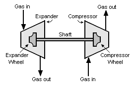
An expansion turbine, also referred to as a turboexpander or turbo-expander, is a centrifugal or axial flow turbine through which a high pressure gas is expanded to produce work that is often used to drive a gas compressor.
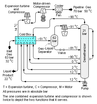
Because work is extracted from the expanding high pressure gas, the expansion is an isentropic process (i.e., a constant entropy process) and the low pressure exhaust gas from the turbine is at a very low temperature, often as low as 200 K (-100 °F) or less. Expansion turbines are very widely used as sources of refrigeration in industrial processes such as the extraction of ethane and natural gas liquids (NGLs) from natural gas,[1] the liquefaction of gases[2][3] and other low-temperature processes.
In 1939, Pyotr Kapitza of Russia suggested the use of a centrifugal turbine for the isentropic expansion of gases to produce refrigeration. Since then, centrifugal expansion turbines have taken over almost 100 percent of the gas liquefaction and other low-temperature industrial requirements.
Applications
Extracting hydrocarbon liquids from natural gas
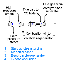
Power recovery in fluid catalytic cracking unit
History
References
- ↑ Demethanzer
- ↑ BOC (NZ) publication: use search function for keyword "expansion"
- ↑ US Department of Energy Hydrogen Program


