Induced gas flotation: Difference between revisions
imported>Milton Beychok (More spacing around the table) |
mNo edit summary |
||
| (One intermediate revision by one other user not shown) | |||
| Line 34: | Line 34: | ||
==Chemical treatment== | ==Chemical treatment== | ||
It is important to note that the treatment of produced water from oil and gas production facilities includes grit screening and removal as well as gravity separations systems such as [[API oil-water separator]]s and [[API oil-water separator|parallel plate oil-water separators]] that considerably reduce the amount of suspended matter (oil and solids) before the water is subjected to induced gas flotation. [[Coagulant|Coagulation]] chemicals such as [[ferrous sulfate]] and [[ | It is important to note that the treatment of produced water from oil and gas production facilities includes grit screening and removal as well as gravity separations systems such as [[API oil-water separator]]s and [[API oil-water separator|parallel plate oil-water separators]] that considerably reduce the amount of suspended matter (oil and solids) before the water is subjected to induced gas flotation. [[Coagulant|Coagulation]] chemicals such as [[ferrous sulfate]] and [[aluminium sulfate]] are often, but not always, used in those pretreatment steps that precede the IGF units. | ||
The IGF units also benefit from the use of chemicals such as [[surfactant]]s and [[polyelectrolytes]]:<ref name=EPA/> | The IGF units also benefit from the use of chemicals such as [[surfactant]]s and [[polyelectrolytes]]:<ref name=EPA/> | ||
| Line 68: | Line 68: | ||
==References== | ==References== | ||
{{reflist}} | {{reflist}}[[Category:Suggestion Bot Tag]] | ||
Latest revision as of 06:00, 1 September 2024
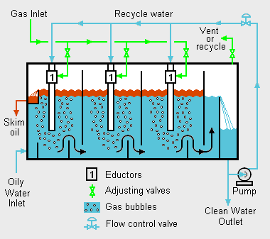
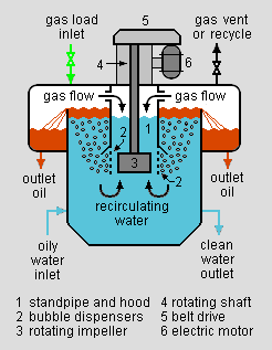
Induced gas flotation (IGF) is a treatment process that clarifies wastewaters (or other waters) by the removal of suspended oil. The removal is achieved by introducing very small bubbles of air or other gases into the water or wastewater. The bubbles adhere to and enhance the buoyancy of the suspended oil which accelerates the rate at which the oil floats to the surface of the water where it can then be skimmed off for removal (see the adjacent drawing).[1]
Induced gas flotation is widely used by the oil and gas industry in onshore and offshore oil and gas production facilities as part of the equipment used to de-oil their wastewaters (called "production water").[1]
A similar process, known as dissolved air flotation (DAF) is commonly used in treating the wastewater effluents from oil refineries, petrochemical and chemical plants, and natural gas processing plants.
Types of flotation processes
There are various types of flotation processes that use dispersed gas bubbles as the flotation agent. The primary difference between the various types is the manner in which the gas bubbles are formed.[1]
Dissolved air flotation (DAF)
In this process, a portion of the clarified wastewater leaving the flotation vessel is pumped into a separate, small pressure vessel (called the air drum) into which compressed air is also introduced. This results in saturating the pressurized effluent water with the air. The air-saturated water stream is recycled to the front of the float tank and flows through a pressure reduction control valve just as it enters the front of the flotation vessel, which results in the air being released in the form of small bubbles.[1][2]
In some installations, an inert gas (such as nitrogen) is used rather than air in order to avoid possibly creating a flammable or explosive condition. In such cases the process is referred to as Dissolved gas flotation (DGF).
Induced gas flotation (IGF)
In this process the gas is drawn (i.e., induced) into the flotation vessel to form bubbles internally within the flotation vessel. There are two-subtypes of the IGF process:[1][3]
- Hydraulic-type IGF: As shown in Fig.1, in this IGF subtype, a portion of the clarified wastewater leaving the flotation vessel is recycled back into the flotation vessel by a pump. The recycled water enters the vessel through an internal pipe that contains an eductor which draws gas into the pipe and mixes it with the wastewater water to form bubbles within the flotation vessel.
- Mechanical-type IGF: As shown in Fig.2, in this IGF subtype, a rotating impeller within the flotation vessel (driven by an electric motor mounted on the vessel exterior) forms a vortex which draws gas into the vessel and mixes it with the wastewater to form bubbles within the flotation vessel. The gas within the the cell is continually circulating.
As mentioned above, induced gas flotation is widely used for de-oiling the wastewaters from onshore and offshore oil and gas production facilities. Since produced raw natural gas is usually present at such facilities, it is often used as the induced gas.
The hydraulic-type IGF is generally less expensive, lower in operating costs and requires less downtime for maintenance than the mechanical-type.[1]
Most IGF units are contained in horizontal vessels. However, there are some vertical versions as well.
Chemical treatment
It is important to note that the treatment of produced water from oil and gas production facilities includes grit screening and removal as well as gravity separations systems such as API oil-water separators and parallel plate oil-water separators that considerably reduce the amount of suspended matter (oil and solids) before the water is subjected to induced gas flotation. Coagulation chemicals such as ferrous sulfate and aluminium sulfate are often, but not always, used in those pretreatment steps that precede the IGF units.
The IGF units also benefit from the use of chemicals such as surfactants and polyelectrolytes:[1]
- Oil-wetted solids settle poorly because the lower density of the oil combined with the higher density of the solid results in the oil-wetted solids having a neutral buoyancy in water. Surfactants (also known as surface active agents) are large organic chemical molecules that contain components which are insoluble in water and components which are soluble in water (i.e., hydrophobic and hydrophilic components) and are capable of reducing the interfacial tension between oil and the solid in an oil-wetted solid particle. Thus, surfactants break apart the oil and the solids so that they can more easily separate from the wastewater.
- Polyelectrolytes are polymers whose repeating units bear an electrolyte group. These groups will dissociate in water to form charged polymers which facilitate the aggregation of suspended oil or solid particles resulting in structures that are more easily attached to the gas bubbles.
The use of chemicals in IGF units is an effective means of increasing their oil removal efficiency.[1]
|
Oil removal performance
In Fig.1, each of the 3 sections containing an eductor is referred to as a "cell". In practice, many IGF units have 4 such cells.[1][3][4]
The oil removal efficiency of a well-designed and well-operated IGF cell ranges from about 55% to about 65%. Thus, four such cells in series can be expected to achieve from 95.9% to more than 98.5% oil removal.[1][3][4]
Most IGF units work best when the wastewater concentration of suspended oil has been reduced (in the preceding treatment units) to no more than 500 ppm by weight (equivalent to 500 mg/L) and preferably less than 50 ppm by weight (equivalent to 50 mg/L). As shown in the adjacent table, for that range of oil in the inlet wastewater, the expected oil content of the outlet water can be expected to range from less than 0.75 mg/L to no more than 20.5 mg/L.
References
- ↑ 1.0 1.1 1.2 1.3 1.4 1.5 1.6 1.7 1.8 1.9 Chapter VIII, Produced Water Characterization, Control and Treatment Technologies Part of the U.S. EPA publication EPA-821-R-96-023, Development Document for Final Effluent Limitations Guidelines and Standards for the Coastal Subcategory of the Oil and Gas Extraction Point Source Category, October 1995
- ↑ M. R. Beychok (1967). Aqueous Wastes from Petroleum and Petrochemical Plants, 1st edition. John Wiley & Sons. Library of Congress Control Number 67019834.
- ↑ 3.0 3.1 3.2 Ken Arnold and Maurice Stewart (2008). Surface Production Operations: Design of Oil Handling Systems and Facilities, 3rd Edition. Gulf Professional Publishing. ISBN 0-7506-7853-4.
- ↑ 4.0 4.1 Tridair™ Hydraulic induced gas flotation

