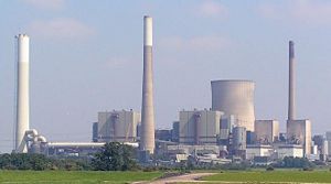
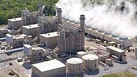
Conventional coal-fired power plant
A conventional coal-fired power plant produces electricity by burning coal in a steam generator that heats water to produce high pressure steam. The steam flows through a series of steam turbines which spin an electrical generator to produce electricity. The exhaust steam from the turbines is cooled, condensed back into water, and returned to the steam generator to start the process over.
Conventional coal-fired power plants are highly complex and custom designed on a large scale for continuous operation 24 hours per day and 365 days per year. Such plants provide most of the electrical energy used in many countries.
Coal transport and delivery
Coal is delivered by highway truck, rail, barge or collier ship. Some plants are even built near coal mines and the coal is delivered from the mines by conveyors or by massive trucks.
A large coal train called a "unit train" may be two kilometers (over a mile) long, containing 100 railcars with 90 metric tons in each one, for a total load of 9,000 metric tons. A large plant under full load requires at least one coal delivery this size every day. Plants may get as many as three to five trains a day, especially in "peak season", during the summer months when power consumption is high. A large coal-fired power plant such as the one in Nanticoke, Canada stores several million metric tons of coal for winter use when delivery via the Great Lakes is not possible.
Modern unloaders use rotary dump devices, which eliminate problems with coal freezing in bottom dump cars. The unloader includes a train positioner arm that pulls the entire train to position each car over a coal hopper. The dumper clamps an individual car against a platform that swivels the car upside down to dump the coal. Swiveling couplers enable the entire operation to occur while the cars are still coupled together. Unloading a unit train takes about three hours.
Shorter trains may use railcars with an "air-dump", which relies on air pressure from the engine plus a "hot shoe" on each car. This "hot shoe" when it comes into contact with a "hot rail" at the unloading trestle, shoots an electric charge through the air dump apparatus and causes the doors on the bottom of the car to open, dumping the coal through the opening in the trestle. Unloading one of these trains takes anywhere from an hour to an hour and a half. Older unloaders may still use manually operated bottom-dump rail cars and a "shaker" attached to dump the coal.
A collier (cargo ship carrying coal) may hold 35,000 metric tons of coal and takes several days to unload. Colliers are large, seaworthy, self-powered ships. For transporting coal in calmer waters, such as rivers and lakes, flat-bottomed vessels called barges pulled by towboats are used.
For startup or auxiliary purposes, a coal-fired power plant may use fuel oil as well. Fuel oil can be delivered to plants by pipeline, tanker, tank car or truck.
Fuel processing
Coal is prepared for use by first crushing the rough coal into pieces less than 5 cm in size. The coal is then transported from the storage yard to in-plant storage silos by rubberized conveyor belts.
In plants that burn pulverized coal, coal from the storage silos is fed into pulverizers ) that grind the crushed coal into the consistency of face powder and mix it with primary combustion air which transports the pulverized coal to the steam generator furnace. A 500 MW coal-fired power plant will have about six such pulverizers, five of which will supply the steam generator at full load with about 225 metric tons per hour.
In plants that do not burn pulverized coal, the crushed coal may be directly fed into cyclone burners, a specific kind of combustor that can efficiently burn larger pieces of coal.
Feedwater heating and deaeration
The feedwater used in the steam generator consists of recirculated condensate water and makeup water. Because the metallic materials it contacts are subject to corrosion at high temperatures and pressures, the makeup water is highly purified in a system of water softeners and ion exchange demineralizers. The makeup water in a 500 MW plant amounts to about 75 litres per minute to offset the small losses from steam leaks in the system.
The feedwater system begins with the condensate water being pumped out of the turbine exhaust steam condenser (commonly referred to as a surface condenser). The condensate water flow rate in a 500 MW coal-fired power plant is about 23,000 litres per minute.
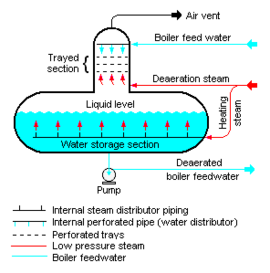
The feedwater plus makeup water flows through intermediate feedwater heaters heated with steam extracted from the steam turbines. Typically, the total feedwater then flows through a deaerator[1][2] that removes dissolved air from the water, further purifying and reducing its corrosivity.
Following the deaeration, the water may be dosed with hydrazine, a chemical that removes the remaining oxygen in the water to below 5 parts per billion (ppb). It is also dosed with pH control agents such as ammonia or morpholine to keep the residual acidity low and thus non-corrosive.
The steam generator
A conventional coal-fired steam generator is a rectangular furnace about 15 metres on a side and 40 metres tall. Its walls are made of a web of high pressure steel boiler tubes.
The deaerated boiler feedwater enters the economizer (see the adjacent diagram) where it is preheated by the hot combustion flue gases and then flows into the boiler steam drum at the top of the furnace. Water from that drum circulates through the tubes in the furnace walls.
Pulverized coal is air-blown into the furnace from fuel nozzles at the four corners and it rapidly burns, forming a large fireball at the center. The thermal radiation of the fireball heats the water that circulates through the boiler tubes in the furnace walls. As the water circulates, it absorbs heat and partially changes into steam at about 362 °C and 190 bar (19 MPa). In the boiler steam drum, the steam is separated from the circulating water. The steam then flow through superheat tubes that hang in the hottest part of the combustion flue gases as they exit the furnace. Here the steam is superheated to about 540 °C before being routed into the high pressure steam turbine.
The steam turbines and the electrical generator
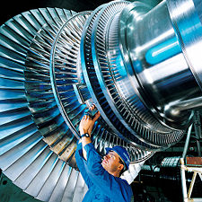
The staged series of steam turbines includes a high pressure steam turbine, an intermediate steam pressure turbine and two low pressure steam turbines. The series of turbines are interconnected to each other and are on a common shaft, with the electrical generator also being on that common shaft.
As steam moves through the system and loses pressure and thermal energy it expands in volume, requiring increasing turbine diameter and longer turbine blades at each succeeding stage. The entire rotating mass may be over 180 metric tons and 30 metres long. It is so heavy that it must be kept turning slowly even when shut down (at 3 rpm) so that the shaft will not bow even slightly and become unbalanced. This is so important that it is one of only major functions to be maintained by the emergency power batteries on site.
Superheated steam from the steam generator flows into the high pressure turbine. The exhaust steam from the high pressure turbine (reduced in pressure and in temperature) returns to the steam generator's reheating tubes where it is reheated back to 540 °C before it flows into the intermediate pressure turbine. The exhaust steam from the intermediate pressure turbine flow directly into the low pressure turbine and the exhaust steam from the low pressure turbines flows into the surface condenser.
The turbine-driven electrical generator, about 10 metres long and 4 metres in diameter, contains a stationary stator and a spinning rotor. In operation, it generates up to 21,000 amperes at 24,000 volts of alternating current (about 500 MW) as it spins at about 3,000 or 3,600 rpm, synchronized to the power grid.
The rotor spins in a sealed chamber cooled with hydrogen gas, selected because it has the highest known heat transfer coefficient of any gas and for its low viscosity which reduces windage losses. This system requires special handling during startup, with air in the chamber first displaced by carbon dioxide before filling with hydrogen. This ensures that a highly explosive hydrogen-oxygen environment is not created.
The power grid frequency is 60 Hz across North America and 50 Hz in Europe, Oceania, Asia (Korea and parts of Japan are notable exceptions) and parts of Africa.
The electricity flows to a distribution yard where transformers step the voltage up to 115, 230, 500 or 765 kV as needed for transmission to its destination.
Steam condensing and cooling towers
The exhaust steam from the low pressure turbines is condensed into water in a water-cooled surface condenser. The condensed water is commonly referred to as condensate. The surface condenser operates at an absolute pressure of about 35 to 40 mmHg (i.e., a vacuum of about 720 to 725 mmHg) which maximizes the overall power plant efficiency.
The surface condenser is usually a shell and tube heat exchanger. Cooling water circulates through the tubes in the condenser's shell and the low pressure exhaust steam is condensed by flowing over the tubes as shown in the adjacent diagram. Typically the cooling water causes the steam to condense at a temperature of about 35 °C. The lower is the condensing temperature, the lower is the vacuum at the exhaust of the low pressure turbine and the higher is the overall plant efficiency. The limiting factor in providing a low condensing temperatures is the temperature of the cooling water and that, in turn, is limited by the prevailing average climatic conditions at the power plant's location.
The condensate from the bottom of the surface condenser is pumped back to be reused as feedwater to the steam generator.
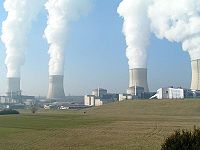
The heat absorbed by the circulating cooling water in the condenser tubes must also be removed to maintain the ability of the water to cool as it circulates. This is done by pumping the warm water from the condenser through either natural draft, forced draft or induced draft cooling towers (as seen in the images to the right) that reduce the temperature of the water by about 11–17 °C and expel the low-temperature waste heat to the atmosphere. The circulation flow rate of the cooling water in a 500 MW unit is about 14.2 m³/s (225,000 US gal/minute) at full load.[3]
The condenser tubes are made of brass or stainless steel to resist corrosion from either side. Nevertheless they may become internally fouled during operation by bacteria or algae in the cooling water or by mineral scaling, all of which inhibit heat transfer and reduce the condenser efficiency. Many plants include an automatic cleaning system that circulates sponge rubber balls through the tubes to scrub them clean without the need to take the system off-line.
The cooling water used to condense the steam in the condenser returns to its source without having been changed other than having been warmed. If the water returns to a local water body (rather than a circulating cooling tower), it is mixed with cool raw water to lower its temperature and prevent thermal shock to aquatic biota when discharged into that body of water.
Another form of condensing system is the air-cooled condenser. Exhaust heat from the low pressure section of a steam turbine flows through the air-cooled condensing tubes which are usually finned and ambient air is directed over the fins by a large fan. Air-cooled condensers typically operate at a higher temperature than water-cooled surface condensers. While reducing the amount of water used in a power plant, air-cooled condensers reduce the efficiency of the power plant.
Diagram of the overall conventional coal-fired power plant
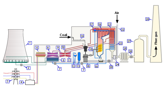
| 1. Cooling tower | 11. High pressure steam turbine | 20. Fan |
| 2. Cooling water pump | 12. Deaerator | 21. Reheater |
| 3. Three-phase transmission line | 13. Feedwater heater | 22. Combustion air intake |
| 4. Step-up transformer | 14. Coal conveyor | 23. Economiser |
| 5. Electrical generator | 15. Coal hopper | 24. Air preheater |
| 6. Low pressure steam turbines | 16. Coal pulverizer | 25. Cold-side Electrostatic precipitator |
| 7. Boiler feedwater pump | 17. Steam drum | 26. Fan |
| 8. Surface condenser | 18. Bottom ash hopper | 27. Flue gas desulfurization scrubber |
| 9. Intermediate pressure steam turbine | 19. Superheater | 28. Flue gas stack |
| 10. Steam control valve |
Stack gas path and clean-up
As the combustion flue gas exits the steam generator, it flows through a heat exchange device where it is cooled by exchanging heat with the incoming combustion air. The device is called an air preheater. The gas exiting the steam generator is laden with fly ash, which are very small ash particles. The flue gas contains nitrogen along with combustion products carbon dioxide (CO2), sulfur dioxide (SO2) and nitrogen oxides (NOx). The fly ash is removed by fabric bag filters or electrostatic precipitators.
After removal of the fly ash, many coal-fired power plants use various flue gas desulfurization (FGD) processes to reduce sulfur dioxide emissions and other processes to reduce nitrogen dioxide emissions. The currently available (2008) technology for flue gas clean-up can remove 99.9% of the fly ash, 99% of the sulfur dioxide and about 90% of the nitrogen dioxides.[4]
However, coal-fired power plants in some parts of the world do not include such processes. Legislation in Europe has been efficient in reducing flue gas pollution. Japan has been using flue gas cleaning technology for over 30 years and the United States has been doing the same for over 25 years. China is now grappling with the problem of flue gas pollutants from coal-fired power plants.
After fly ash removal and any other flue gas cleaning processes, the flue gas exits to the atmosphere via tall flue gas stacks. A typical flue gas stack may be about 150 to 250 metres tall to disperse the remaining flue gas components in the atmosphere.
In the United States and a number of other countries, air pollution dispersion modeling[5] studies are required to determine the flue gas stack height needed to comply with the local air pollution regulations. The United States also requires the height of a flue gas stack to comply with what is known as the "Good Engineering Practice (GEP)" stack height.[6][7] In the case of existing flue gas stacks that exceed the GEP stack height, any air pollution dispersion modeling studies (to determine environmental impacts) for such stacks must use the GEP stack height rather than the actual stack height.
Supercritical steam generators
Above the critical point for water of 374 °C and 22 MPa, there is no phase transition from water to steam, but only a gradual decrease in density. Boiling does not occur and it is not possible to remove impurities via steam separation.
Supercritical steam generators operating at or above the critical point of water are referred to as once-through plants because boiler water does not circulate multiple times as in a conventional steam generator. Supercritical steam generators require additional water purification steps to ensure that any impurities picked up during the cycle are removed. This purification takes the form of high pressure ion exchange units called condensate polishers between the steam condenser and the feedwater heaters.
Conventional coal-fired power plants operate at subcritical conditions and typically achieve 34–36% thermal efficiency. Supercritical coal-fired power plants, operating at 565 °C and 243 bar (24.3 MPa) have efficiencies in the range of 38–40%. New "ultra critical" designs, operating at 700–720 °C and 365–385 bar (36.5–38.5 MPa), are expected to achieve 44–46% efficiency.[4]
Alternatives to coal-fired power plants
Alternatives to coal-fired power plants include using other fossil fuels (natural gas or fuel oil), nuclear power plants, geothermal power plants, hydroelectric power plants, solar power plants, wind power plants and tidal power plants.
Environmental impacts
(This section is currently being developed)
References
- ↑ Pressurized deaerators
- ↑ Tray deaerating heaters
- ↑ EPA Workshop on Cooling Water Intake Technologies Arlington, Virginia John Maulbetsch, Maulbetsch Consulting Kent Zammit, EPRI. 6 May 2003. Retrieved 10 September 2006.
- ↑ 4.0 4.1 Dr. James Katzer et al and MIT Coal Energy Study Advisory Committee (2007). The Future of Coal. Massachusetts Institute of Technology. ISBN 0-615-14092-0. The Future of Coal
- ↑ Beychok, Milton R. (2005). Fundamentals Of Stack Gas Dispersion, 4th Edition. author-published. ISBN 0-9644588-0-2. www.air-dispersion.com
- ↑ Guideline for Determination of Good Engineering Practice Stack Height (Technical Support Document for the Stack Height Regulations), Revised, 1985, EPA Publication No. EPA–450/4–80–023R, U.S. Environmental Protection Agency (NTIS No. PB 85–225241)
- ↑ Lawson, Jr., R. E. and W. H. Snyder, 1983. Determination of Good Engineering Practice Stack Height: A Demonstration Study for a Power Plant, 1983, EPA Publication No. EPA–600/3–83–024. U.S. Environmental Protection Agency (NTIS No. PB 83–207407)
