User:Milton Beychok/Sandbox
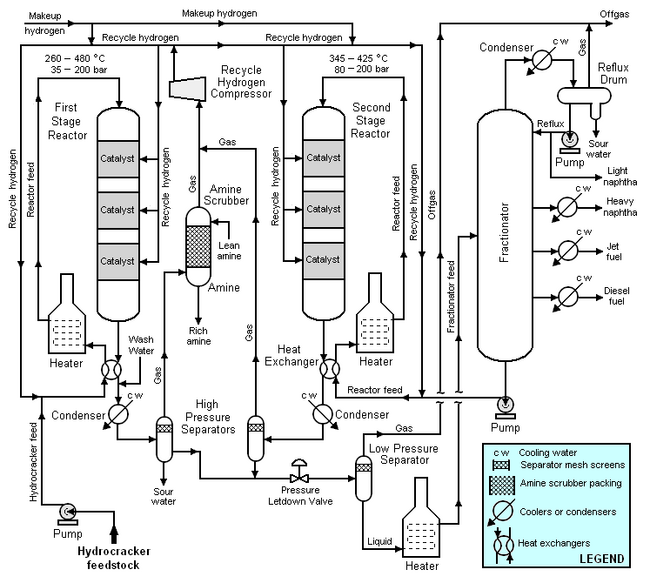
Typical flow diagram of a two stage hydrocracker
The high-boiling, high molecular weight hydrocarbons used as feedstocks for catalytic hydrocrackers include what are commonly referred to as atmospheric gas oil from atmospheric crude oil distillation units, vacuum gas oil from vacuum distillation units, and cycle oil from fluid catalytic cracking units. For describing the hydrocracking process depicted in the typical flow diagram below, the feedstock will be referred to as simply gas oil.
The gas oil from the feedstock pump is mixed with a stream of high-pressure hydrogen and then flows through a heat exchanger where it is heated by the hot effluent reaction products from the hydrocracker's first stage reactor. The feedstock is then heated further in a fuel-fired heater before it enters the top of first stage reactor and flows downward through three beds of catalyst. The temperature and pressure conditions in the first stage reactor depend upon the specific licensed hydrocracker design, the feedstock properties, the desired products, the catalyst being used and other variables. As a broad generality, the pressure in the first stage reactor may range from 35 to 200 bar and the temperature may range from 260 to 480 °C.
After the effluent reaction product stream from the reactor bottom is cooled by the incoming gas oil feedstock, it is injected with wash water, partially condensed in a water-cooled condenser and routed into a high-pressure vapor-liquid separator for separation into three phases: hydrogen-rich gas, hydrocarbon liquid and water. Sulfur and nitrogen compounds in the gas oil feedstock are converted into gaseous hydrogen sulfide and ammonia by the hydrogenation that takes place in the first stage reactor. The purpose of the wash water is to dissolve some of the hydrogen sulfide and ammonia gases present in the first stage reaction product stream. The resulting aqueous solution of ammonium hydrosulfide (NH4HS) is referred to as sour water and is typically routed to a sour water stripper elsewhere in the petroleum refinery. The sour water stripper removes hydrogen sulfide from the sour water and that hydrogen sulfide is subsequently converted to endproduct elemental sulfur in a Claus proces unit.
The hydrogen-rich gas from the high-pressure separator is routed through an amine scrubber where it is contacted with an aqueous amine solution[1] to absorb and remove residual hydrogen sulfide in the gas. The rich amine solution (containing the absorbed hydrogen sulfide) is typically routed to a central amine gas treating unit elsewhere in the refinery.
The hydrocarbon liquid phase from the high-pressure separator flows through a pressure letdown (i.e., pressure reduction) valve and into a low-pressure separator. The reduction in pressure partially vaporizes (see flash evaporation) the liquid. The resulting vapor (referred to as offgas) is routed to a central amine gas treating unit elsewhere in the refinery. The hydrocracked the enproducts of hydrocarbon liquid phase from the low-pressure separator is heated in a fuel-fired heater and fed into the fractionator.
The fractionator is a continuous distillation tower that that separates the hydrocracked hydrocarbon stream into naphtha, jet fuel (or kerosene) and diesel oil. The offgas from the tower's associated reflux drum joins the offgas from the low-pressure separator.
Not all of the feedstock hydrocarbons to the first stage reactor are hydrocracked (i.e., converted) into lower-boiling, lower molecular weight hydrocarbons. The bottom stream from the fractionator consists of the unconverted hydrocarbons from the first stage reactor and that stream is mixed with high pressure hydrogen and recycled as feed to the second stage reactor. It is first heated by the hot effluent reaction products from the second stage reactor. The recycled feed is then heated further in a fuel-fired heater before it enters the top of second stage reactor and flows downward through three beds of catalyst. The temperature and pressure conditions in the second stage reactor depend upon the same variables as determine the conditions in the first stage reactor. As a broad generality, the prNMessure in the second stage reactor may range from 80 to 200 bar and the temperature may range from 345 to 425 °C.
After the effluent reaction product stream from the second stage reactor bottom is cooled by the incoming recycle feed, it is partially condensed in a water-cooled condenser and routed into second high-pressure vapor-liquid separator for separation into two phases: hydrogen-rich gas and hydrocarbon. No water washing of the second stage reactor effluent is needed because the second stage reactor effluent is essentially free of hydrogen sulfide and ammonia gases. For the same reason, the gas from the second high-pressure separator does not require amine scrubbing to remove hydrogen sulfide.
The two hydrogen-rich gas streams (the amine-scrubbed gas from the first high-pressure separator and the gas from second high-pressure separator) are joined and then compressed and recycled for use in both the first and second stage reactor systems.
The hydrogenation of sulfur and nitrogen compounds in the first stage reactor requires the consumption of hydrogen. Likewise, the saturation of olefins and aromatics, in both the first stage and second stage reactors, to form paraffinic hydrocracked products consumes hydrogen.
- ↑ The amines most commonly used for removing hydrogen sulfide from refinery gases area monoethanol amine (MEA), diethanolamine (DEA) and methyldiethanolamine (MDEA)
